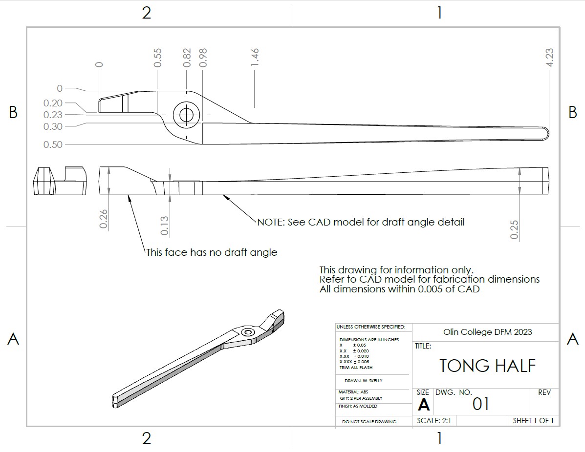
For our final project for Design for Manufacture, my team produced a run of injection molded tongs. We
designed and manufactured the parts and the molds in-house using Olin's machine shop.
The objectives of the design project (relevant design requirements) were:
- Make a set of injection molded tongs capable of manipulating small objects in
tight spaces
- Design so that each set of tongs consist of 2 identical injection molded parts
(in addition to off-the-shelf fastening components)
- Leverage high-volume manufacturing techniques
- Design and machine our molds
The skills I developed during this project include:
- Designing parts for injection molding
- Plastics simulation for injection molded parts
- Designing and fabricating molds for injection molding
- CAM (HSM-works) for 3D CNC machining operations
- Use of engineering running fit
- Operation of injection molding machine
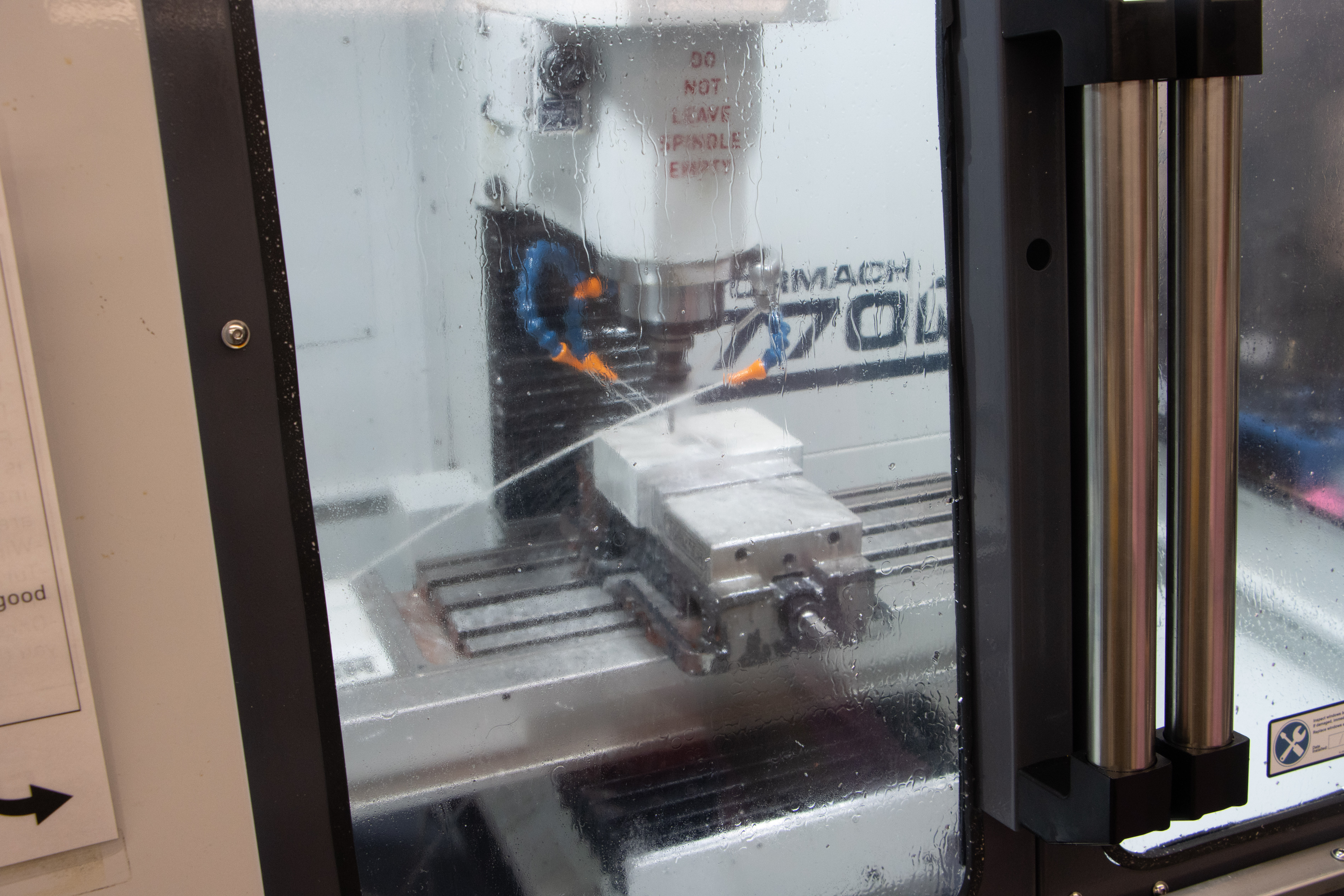
Machining the molds in Tormach CNC
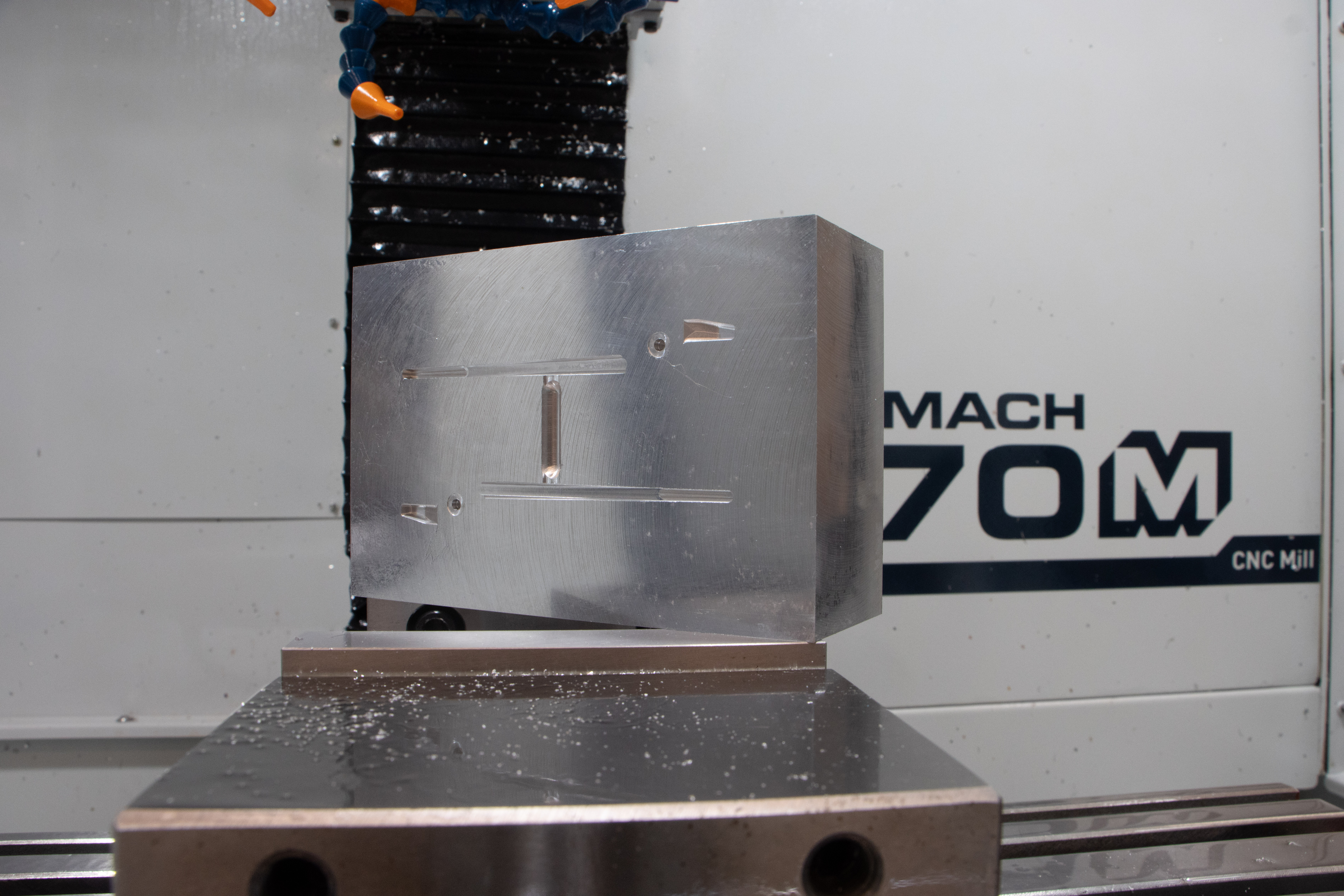
Top half of the mold
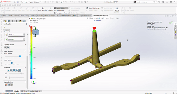
Solidworks plastics simulation of mold flow
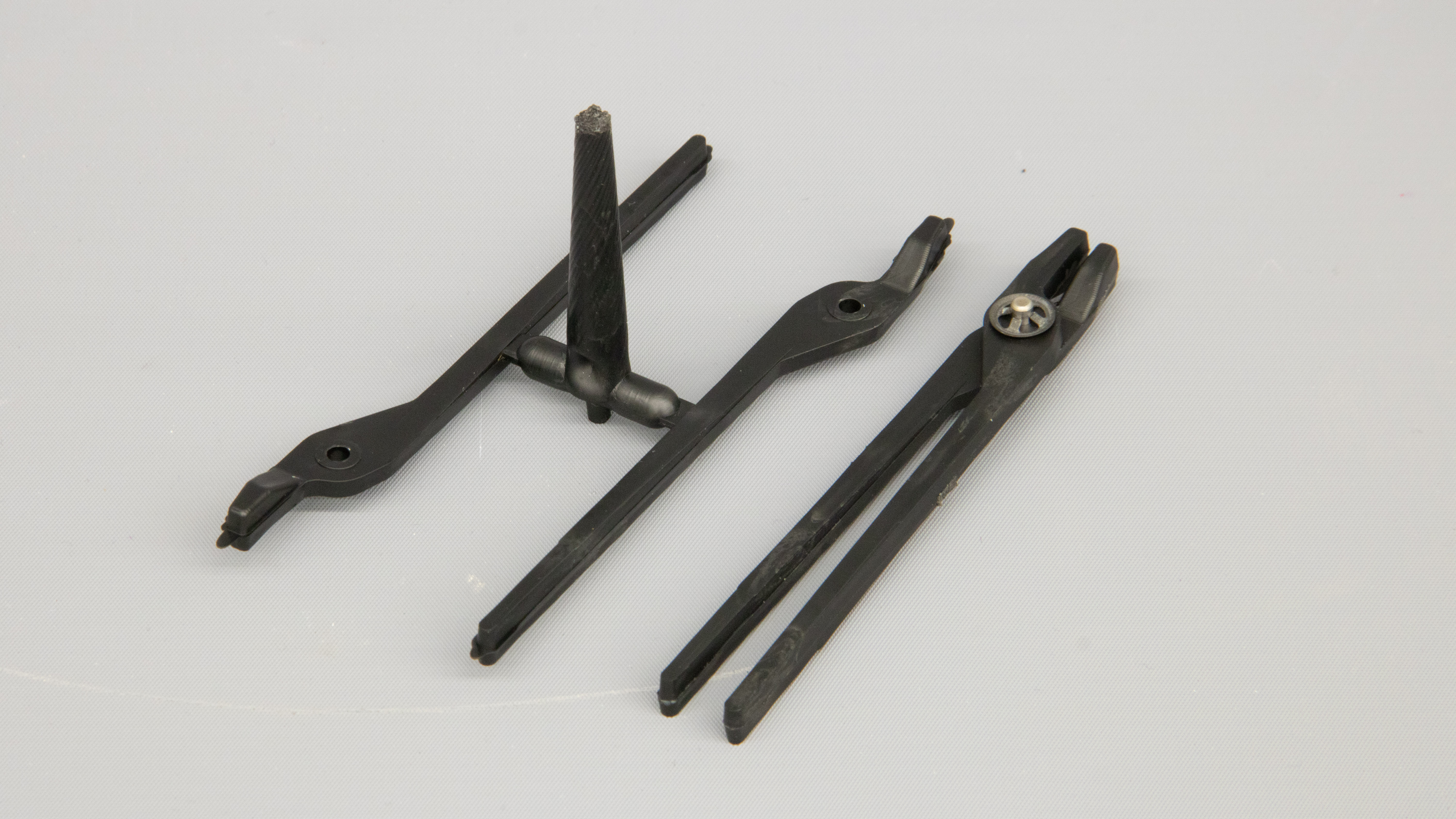
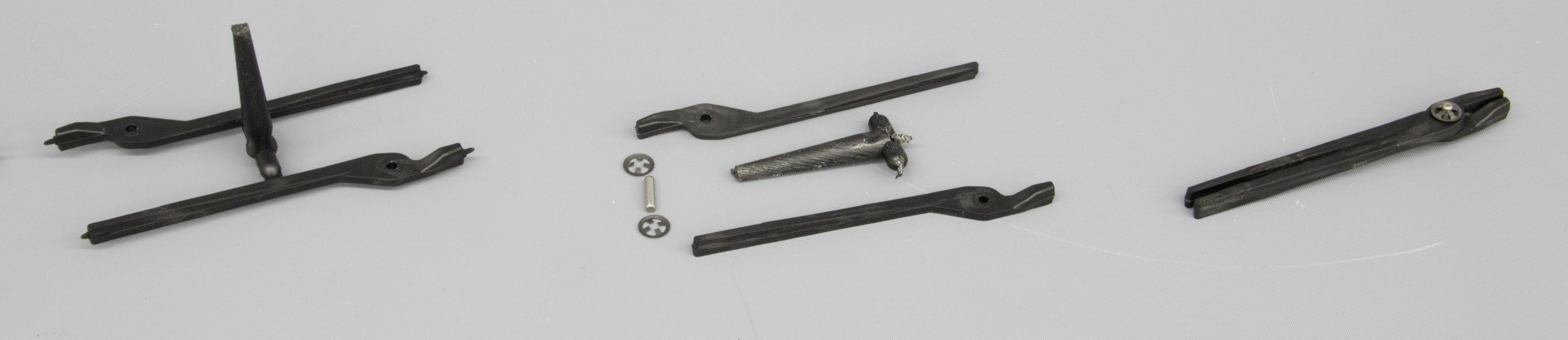
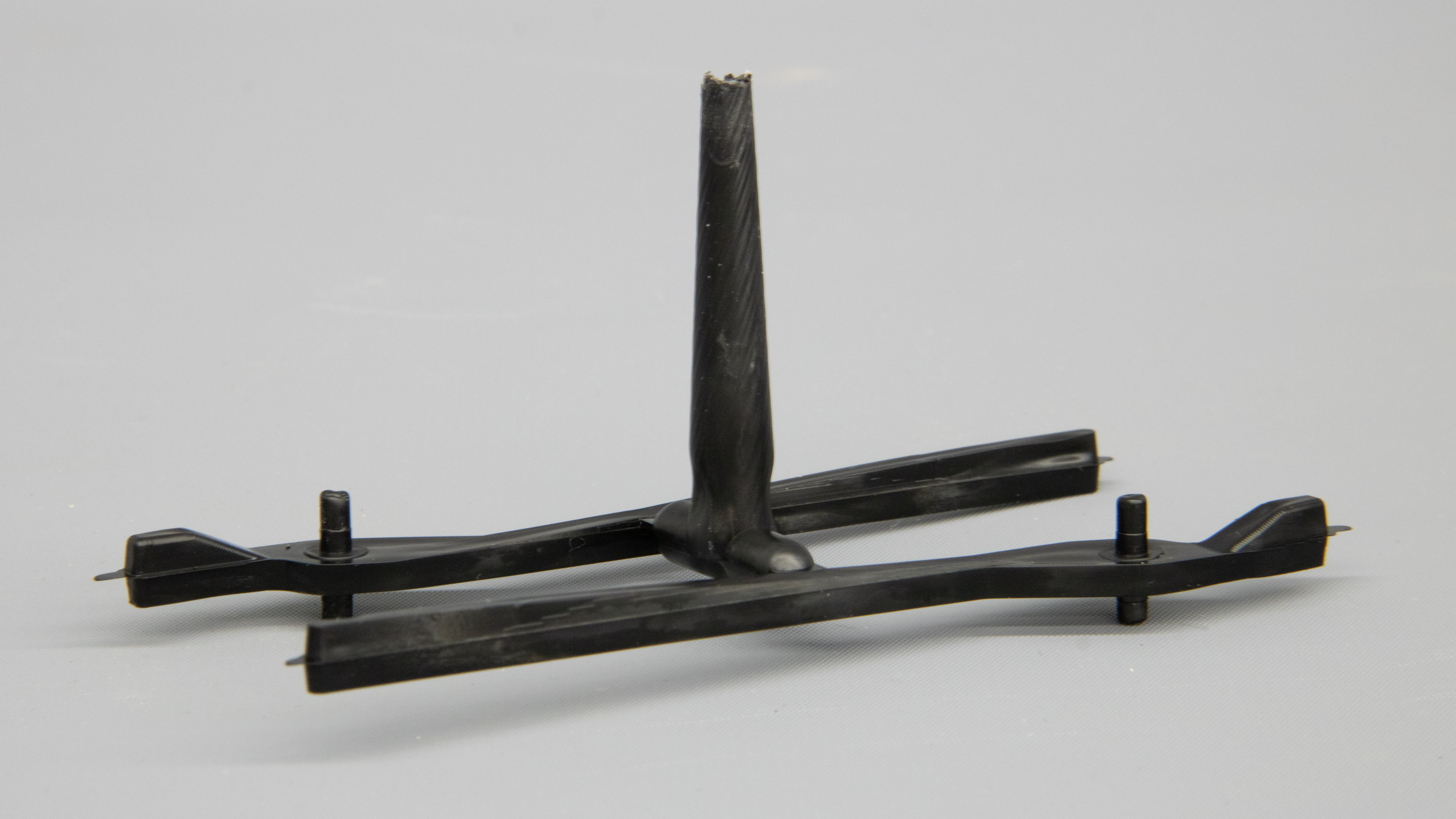
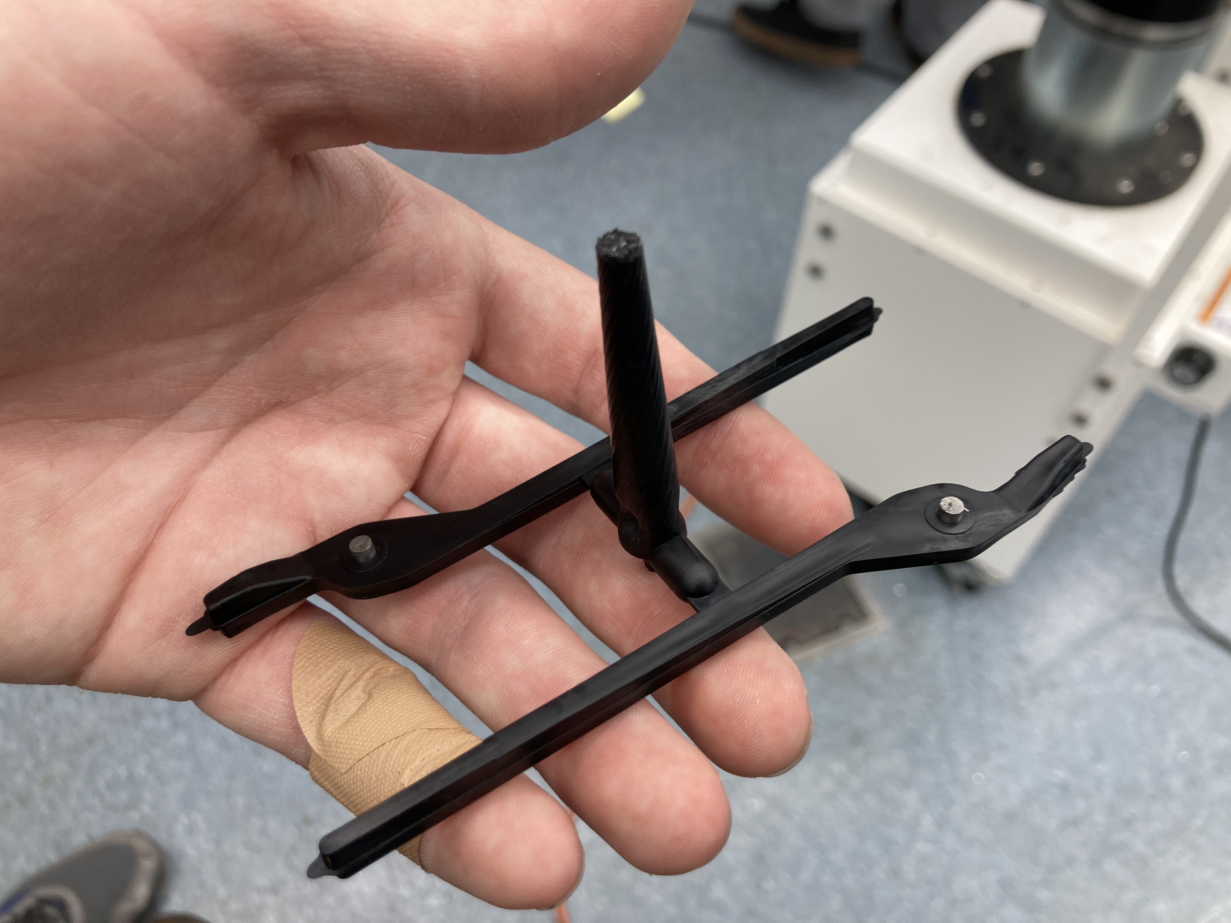
Injection-molded tree fresh out of the machine with over-molded pins not yet
removed.
The final design of the tongs works great, and can pick up small objects. To achieve this, we overcame several challenges along the way,
including:
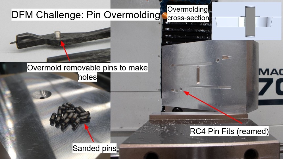
Molding Through Holes via Overmolding
In order to make through holes for the hinge pin without a side-action (which is outside the capability of our molding
equipment), we needed a creative solution. We wound up overmolding a set of pins that fit loosely between the two mold halves
(RC4 running fit). These pins are then removed from the molded part to leave the through hole.
To get the pins to fit between our
mold halves, we needed to beltsand them down to size. In a hypothetical future iteration, the molds could be re-designed or re-machined
to accept a standard length pin. Since these pins are re-usable, however, the extra labor of beltsanding them is offset over the entire
production run.
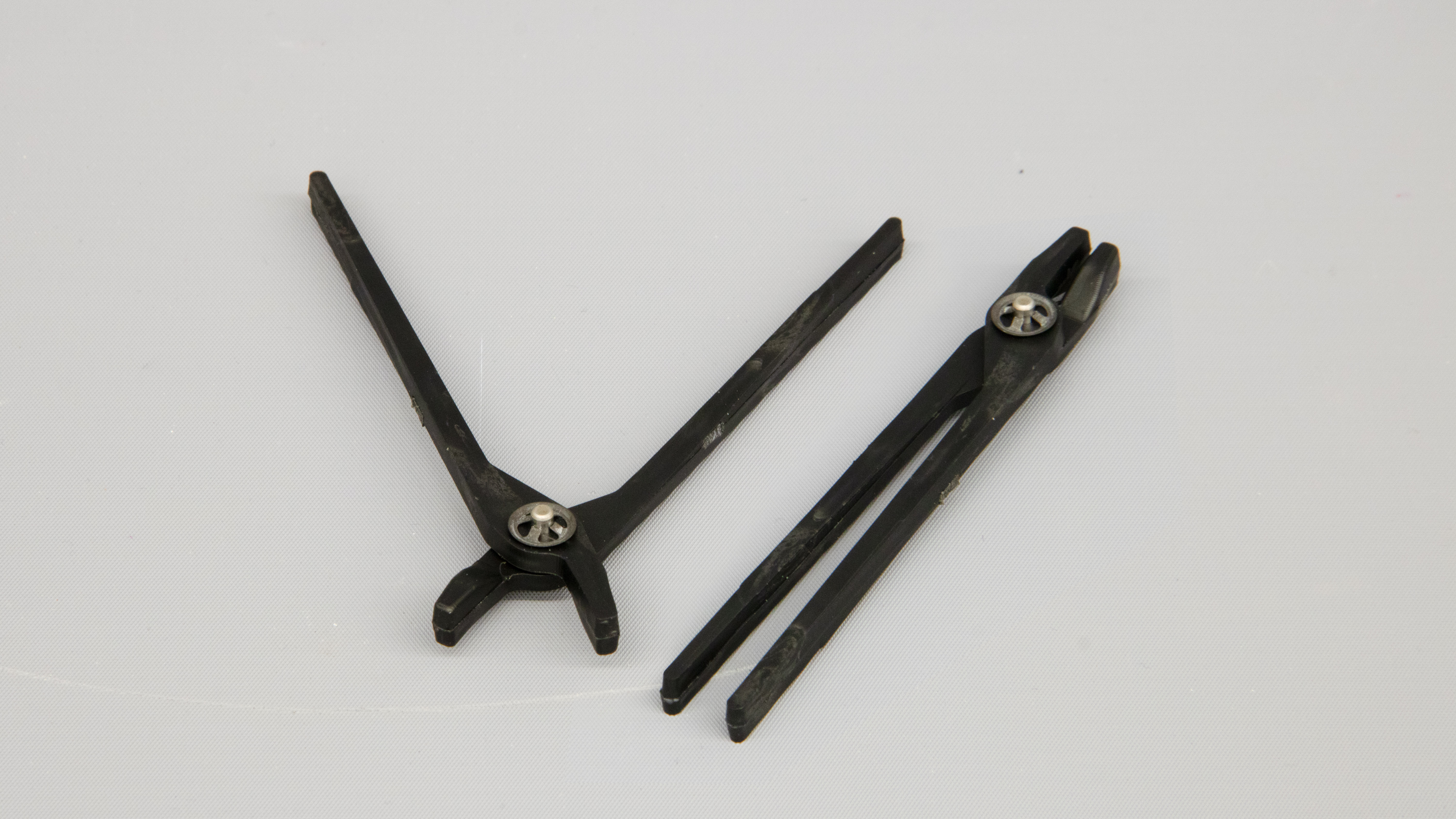
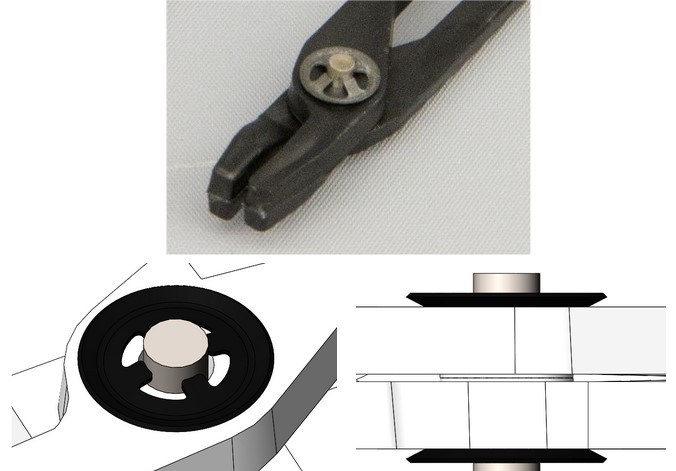
Hinge Pin Retention
To keep the hinge pins axially constrained and retained on the molded part was a detail where design for assembly and manufacture
were very important. A typical low-volume solution would be a C-clip or E-clip; however, these require the hinge pin to have features
machined into it. To be able to use a bear pin, we retained the pin with Push-On External Retaining Rings. These retaining rings
hold the pin in place without needing to modify the dowel pin for the hinge.
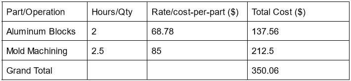
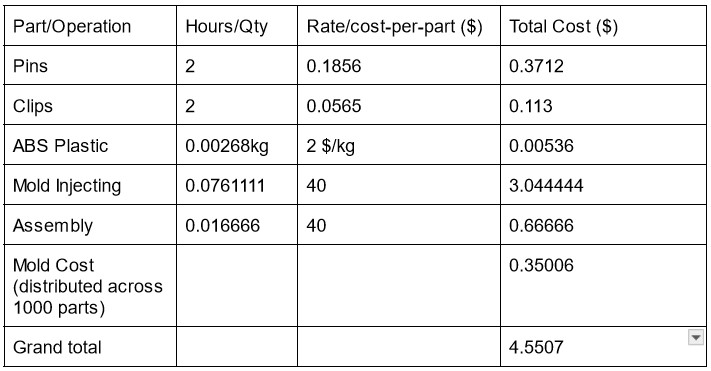
The original design uses two clips and one pin. Using the principle of theoretical minimum part count, the design can be simplified
by molding a pin feature into one half. This version of the design only needs one retaining ring, and no extra pin part. The tradeoff
is that the strength of the joint and quality of the part is reduced. Looking at the BOM/cost analysis for this part, we can see
that the cost of the pin and clips is significantly less than the injection labor; therefore, the team decided it was worth it to increase
quality by using a seperate pin part.
Optimizing Molding Operation
Dialing in the molding parameters took some experimentation. To speed up the experimentation process, we ran several trial shots without
the over-molding pins present. For these trial runs, we discovered a balance between flashing and short-shots. We decided to err on the side
of too long of a shot time and remove the flashing with post-processing. We judged that the cost of failure of a short shot (scrapping the part)
was worse than adding an extra few seconds to trim flashing. We also tuned parameters to deal with sink marks. To reduce sink marks,
we increased the cooling time.
One cause of flashing was that our air vents were a bit large. In a future iteration, we could use smaller air vents to reduce the amount
of post-processing required.